Sections of the site
Editor's Choice:
- What fluxes to use for soldering microcircuits Flux or acid for soldering what to choose
- What fluxes to use for soldering microcircuits What flux is preferable when soldering
- How to increase DC and AC voltage Step-up voltage converter from 3 to 5
- Programs for drawing electrical circuits
- Powerful voltage converters 12v 220v
- Seven-segment indicator control
- High voltage and more
- Wiring diagrams for free
- DIY flower beds from improvised means Country flower beds from improvised materials
- The simplest alarm from a syringe
Advertising
| Powerful voltage converters 12v 220v. |
|
To connect household appliances to the on-board electrical system of a car, an inverter is required that can increase the voltage from 12 V to 220 V. They are available in sufficient quantities on store shelves, but their price is not encouraging. For those who are a little familiar with electrical engineering, it is possible to assemble a 12-220 volt voltage converter with their own hands. We will analyze two simple schemes. Converters and their typesThere are three types of 12-220 V converters. The first one is 220 V from 12 V. Such inverters are popular with motorists: you can connect standard devices through them - TVs, vacuum cleaners, etc. Reverse conversion - from 220 V to 12 - is required infrequently, usually in rooms with severe operating conditions (high humidity) to ensure electrical safety. For example, in steam rooms, pools or bathrooms. In order not to risk, the standard voltage of 220 V is reduced to 12 using the appropriate equipment. The third option is, rather, a stabilizer based on two converters. First, the standard 220 V is converted to 12 V, then back to 220 V. This double conversion allows you to have an ideal sine wave at the output. Such devices are necessary for the normal operation of most electronically controlled household appliances. In any case, during installation, it is strongly advised to power it through such a converter - its electronics are very sensitive to the quality of the power supply, and replacing the control board costs about half the boiler. Pulse converter 12-220V to 300 WThis circuit is simple, parts are available, most of them can be taken from a computer power supply or bought at any electronics store. The advantage of the circuit is the ease of implementation, the disadvantage is the non-ideal sine wave at the output and the frequency is higher than the standard 50 Hz. That is, devices requiring power supply cannot be connected to this converter. Not particularly sensitive devices can be connected directly to the output - incandescent lamps, an iron, a soldering iron, charging from a phone, etc. The presented circuit in normal mode produces 1.5 A or pulls a load of 300 W, to a maximum of 2.5 A, but in this mode, transistors will noticeably heat up.
The circuit was built on the popular PWM controller TLT494. Field-effect transistors Q1 Q2 must be placed on radiators, preferably separate ones. When installing on a single radiator, lay an insulating gasket under the transistors. Instead of those indicated on the IRFZ244 diagram, you can use IRFZ46 or RFZ48 that are similar in characteristics. The frequency in this 12 V to 220 V converter is set by resistor R1 and capacitor C2. The ratings may differ slightly from those indicated in the diagram. If you have an old non-working power supply for a computer, and it has a working output transformer, you can put it in the circuit. If the transformer is inoperative, remove the ferrite ring from it and wind the windings with a copper wire with a diameter of 0.6 mm. First, the primary winding is wound - 10 turns with a lead from the middle, then, on top - 80 turns of the secondary. As already mentioned, such a 12-220 V voltage converter can only work with a load that is insensitive to power quality. In order to be able to connect more demanding devices, a rectifier is installed at the output, at the output of which the voltage is close to normal (diagram below).
The diagram shows high-frequency diodes of the HER307 type, but they can be replaced with the FR207 or FR107 series. Capacities are desirable to choose the specified value. Chip InverterThis 12-220 V voltage converter is assembled on the basis of a specialized KR1211EU1 microcircuit. This is a pulse generator that is taken from outputs 6 and 4. The pulses are antiphase, there is a small time gap between them - to prevent the simultaneous opening of both keys. The microcircuit is powered by a voltage of 9.5 V, which is set by a parametric stabilizer on a D814V zener diode. Also in the circuit there are two field-effect transistors of increased power - IRL2505 (VT1 and VT2). They have a very low open output channel resistance - about 0.008 ohms, which is comparable to the resistance of a mechanical key. Permissible direct current - up to 104 A, pulse - up to 360 A. Such characteristics really allow you to get 220 V at a load of up to 400 W. It is necessary to install transistors on radiators (with a power of up to 200 W, it is possible without them).
The pulse frequency depends on the parameters of the resistor R1 and the capacitor C1, a capacitor C6 is installed at the output to suppress high-frequency emissions. It is better to take the transformer ready. In the circuit, it turns on the other way around - the low-voltage secondary winding serves as the primary, and the voltage is removed from the high-voltage secondary. Possible replacements in the element base:
When installing the circuits for connecting a transformer, transistors and connecting to a 12 V source, it is necessary to use large-section wires - the current here can reach high values (with a power of 400 W up to 40 A). Pure sine inverter outputConverter circuits are complicated even for experienced radio amateurs, so making them yourself is not at all easy. An example of the simplest circuit is below.
In this case, it is easier to assemble a similar converter from ready-made boards. How - see the video. There are several reasons why the owner needs to create a new voltage converter. Its main purpose is to provide a mains voltage of 220V from the initial value of 12 watts. Many amateurs make 12 220 V inverters with their own hands, because. quality converters are not cheap. Before assembling the device, it is necessary to study the materials explaining the mechanism of its use. Scope of converters 12 220 VAs the battery is used, its charge level decreases. The converter stabilizes the voltage while traveling, in the absence of electricity.
The 12 220 V inverter will allow the owner to improve the engineering structures in the house. The power of the device for converting current is selected depending on the total value of the load being operated. The process of its consumption is taken into account: reactive and active. The reactive load does not consume all the received energy, so the total power exceeds its active value. A pure sine wave inverter is used to connect tools with a total power of 3 kW. Significant fuel savings are provided by the use of a voltage converter and a mini-power plant. The following consumers are connected to the inverter:
Back to index Advantages of the device for voltage conversion
Inverters have won a respectful attitude to their work, because they have a number of undoubted advantages. The device works silently, does not clog the surrounding area with exhaust gases. Maintenance of the device is minimal: there is no need to check the pressure in the engine. The inverter has a slight mechanical wear, allows you to connect any consumers. The 12 220 V inverter operates at increased power on the KR121 EU, has a high efficiency. When assembling an inverter with a driver as a multivibrator, the advantages of the converter are expressed in the availability and simplicity of the device. The dimensions of the product are compact, repair is not difficult, and operation is possible at low temperatures. Back to index Homemade converter 12 220 V and the general principle of its creation
In the radio components market, most inverters operate using high frequencies. Pulse inverters have completely replaced the classic circuits using transformers. The K561TM2 microcircuit consists of two D-flip-flops, which contain two inputs R and S. It was created using CMOS technology and is enclosed in a plastic case. The inverter master oscillator is mounted on the basis of K561TM2, using the DD1 device for operation. For the frequency divider, a DD1.2 trigger is mounted. The amplifying stage receives signals from the microcircuit. KT827 transistors are selected for work. In their absence, KT819 GM transistors or field semiconductors - IRFZ44 are used. The sine wave generator for the 12 220 V inverter operates at high frequency. To form a circuit with dimensions of 50 Hz, a secondary winding is used and a capacitor and load are connected in parallel. When any device is connected, the inverter creates a voltage conversion to 220 V. The scheme has one significant drawback - the imperfect form of the output parameters. The K561TM2 chip is duplicated by K564TM2. An increase in the power of the converter is achieved by selecting more intense transistors. Pay attention to the capacitor installed at the output. It has a voltage of 250 V. Back to index Building a transducer using the latest parts
Home-made inverters function stably, at the output the transistors are powered by an amplified main generator. Elements of the KT819GM series are used, mounted on a large radiator. To create a converter, a simplified scheme is used. In the process of work, they acquire the necessary materials:
The KR12116U1 microcircuit has a feature: it contains two channels for adjusting the switches and easily copes with the construction of simple voltage converters. The microcircuit at a temperature of +25 ° C gives the voltage limits of 3 and 9 V. The frequency of the master oscillator is determined by the parameters of the elements in the circuit. IRL2505 transistors are installed for use at the output. It receives a signal, the level of which allows you to adjust the output transistors. The formed low level does not allow the transistors to go from closed to another state. As a result, the occurrence of an instantaneous passage of current after the simultaneous opening of the keys is completely eliminated. When a high level hits pin 1, the pulse generation is turned off. In the diagram, pin 1 is connected to the common wire.
For the installation of a push-pull cascade, a transformer T1 and two transistors are used: VT1 and VT2. In the open channel, a resistance of 0.008 ohms is observed. It is insignificant, so the power of the transistors is small, even when passing a large current. The output transformer, which has a power of 100 W, allows the use of IRL2505 current up to 104 A, and the pulse is 360 A.
With an output power of up to 200 W, they refuse to install transistors on radiators. It should be noted that the electric current at a power of 400 W can reach 40 A. In this article, you can find detailed step-by-step instructions for making a 220V 50Hz AC inverter from a 12V car battery. Such a device is capable of delivering power from 150 to 300W. The scheme of this device is quite simple..
This circuit works on the principle of Push-Pull converters. The heart of the device will be the CD-4047 board, which works as a master oscillator, and also controls field-effect transistors that operate in key mode. Only one transistor can be open, if two transistors are open at the same time, then a short circuit will occur, as a result of which the transistors will burn out, this can also happen in case of improper control.
The CD-4047 board is not designed for high-precision control of field-effect transistors, but it copes with this task perfectly. Also, for the operation of the device, you will need a transformer from an old 250 or 300 W UPS with a primary winding and a mid-point connection plus from the power source.
The transformer has a fairly large number of secondary windings, you will need to measure all the taps with a volt/ohmmeter and find the 220V mains winding. The wires we need will give out the highest electrical resistance of approximately 17 ohms, you can remove the extra layering.
Before you start soldering, it is advisable to double-check everything again. It is recommended to choose transistors with the same batch and the same characteristics, the capacitor of the driving circuit often has a small leakage and a narrow tolerance. Such characteristics are determined by a tester for transistors.
Since the CD-4047 board has no analogues, it is necessary to purchase it, but if necessary, field-effect transistors can be changed to n-channel ones with a voltage of 60V and a current of at least 35A. Suitable from the IRFZ series. Also, the circuit can work using bipolar transistors at the output, but it should be noted that the power of the device will become much less when compared with the circuit that uses "field workers".
Gate limiting resistors should be 10-100 ohm, but 22-47 ohm resistors with a power of 250 mW are preferable.
Often the driving circuit is assembled exclusively from the elements indicated in the diagram, which has fine settings for 50Hz.
If you assemble the device correctly, it will work from the first seconds, but when you first start it is important to play it safe. To do this, instead of a fuse (see the diagram), you need to install a resistor whose value is 5-10 Ohms or a 12V light bulb in order to avoid the explosion of transistors if mistakes were made.
If the device is stable, then the transformer will make a sound, but the keys will not heat up. If everything works correctly, the resistor (bulb) must be removed, and power is supplied through the fuse. On average, the inverter consumes energy when the robot is idling from 150 to 300 mA, depending on which power source and type of transformer. Then you need to measure the output voltage, the output should be about 210-260V, this is considered a normal indicator, since the inverter does not have stabilization. Next, you need to check the device by connecting a 60-watt light bulb under load and letting it work for 10-15 seconds, the keys will heat up a little during this time, since there are no heat sinks on them. The keys should be heated evenly, in case of uneven heating, you need to look for where mistakes were made. We supply the inverter with the Remote Control function
The main positive wire should be connected to the middle point of the transformer, but in order for the device to start working, a low-current plus must be connected to the board. This will start the pulse generator.
A couple of suggestions for installation. Everything is installed in the computer power supply case, the transistors should be installed on separate radiators.
If a common heat sink is installed, be sure to isolate the transistor case from the heatsink. The cooler is connected to the 12V bus.
One of the significant drawbacks of this inverter is the lack of protection against a short circuit, and if it happens, then all transistors will burn out. In order to prevent this, it is imperative to install a 1A fuse at the output.
To start the inverter, a button of low power is used, through which a plus will be supplied to the board. The busbars of the transformer should be fixed directly to the heatsinks of the transistors.
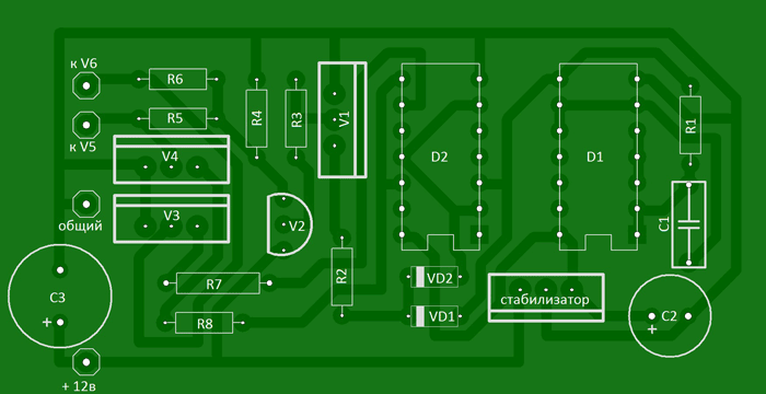
If you connect an energy meter to the output of the converter, you can see on it that the outgoing frequency and voltage are within the allowable range. If you get a value greater or less than 50Hz, you need to adjust it using a multi-turn variable resistor, it is installed on the board. I propose a circuit for a voltage converter (inverter) 12 / 220V (power up to 500 watts), powered by a 12V battery, which can be useful in a car and at home for lighting, to power a TV, a small refrigerator, etc. The circuit is assembled on two microcircuits of the 155th series and six transistors. In the output stage, field-effect transistors are used, which have a very low resistance in the open state, which increases the efficiency of the converter and eliminates the need to install them on radiators of too large area.
Let's deal with the operation of the circuit: (see diagram and diagram). On the D1 chip, a rectangular pulse generator is assembled, the repetition rate of which is about 200 Hz - diagram "A". From pin 8 of the microcircuit, the pulses are fed further to the frequency dividers assembled on the elements D2.1 - D2.2 of the D2 microcircuit. As a result, at pin 6 of the D2 chip, the pulse repetition rate becomes half as much - 100 Hz - diagram "B", and at pin 8 the pulses become equal to a frequency of 50 Hz - diagram "C". Non-inverted pulses of 50 Hz are taken from pin 9 - diagram "D". On the diodes VD1-VD2, an "OR" logic circuit is assembled. As a result, the pulses taken from the pins of the microcircuits D1 pin 8, D2 pin 6 form a pulse corresponding to the "E" diagram on the cathodes of the diodes. The cascade on transistors V1 and V2 serves to increase the amplitude of the pulses necessary for the full opening of the field-effect transistors. Transistors V3 and V4, connected to outputs 8 and 9 of the D2 chip, open in turn, thereby blocking one field-effect transistor V5, then another V6. As a result, the control pulses are formed in such a way that there is a pause between them, which eliminates the possibility of through current flowing through the output transistors and significantly increases the efficiency. Diagrams "F" and "G" show the generated control pulses of transistors V5 and V6. A correctly assembled converter starts working immediately after power is applied. When setting up, you should connect a frequency meter to the output of the device and set the frequency to 50-60 Hz by selecting resistor R1, and, if necessary, capacitor C1.
About details
List of radio elements
|


Popular:

New
- What flux to use for soldering microcircuits Which flux is preferable when soldering
- How to increase DC and AC voltage Step-up voltage converter from 3 to 5
- Programs for drawing electrical circuits
- Powerful voltage converters 12v 220v
- Seven-segment indicator control
- High voltage and more
- Wiring diagrams for free
- DIY flower beds from improvised means Country flower beds from improvised materials
- The simplest alarm from a syringe
- Decorative grille for the battery: do-it-yourself screen Do-it-yourself screen for the heating battery


